
How Does Wind Load Affect Racks in Clad-Rack Warehouses?
How Does Wind Load Affect Racks in Clad-Rack Warehouses?
How Does Wind Load Affect Racks in Clad-Rack Warehouses?
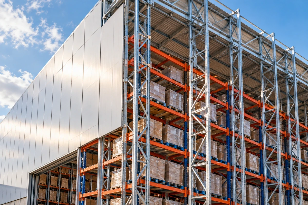
In a clad rack warehouse, there is no separate building structural system; wind loads acting on the facade and roof transfer directly to the rack uprights, creating uplift/tension on the anchors through horizontal forces and roof suction. Terrain, topography, and internal pressure are decisive in the calculation. Empty rack rows and the assembly phase with open facades represent the riskiest conditions.
How does wind load in a clad-rack warehouse affect rack uprights, anchors, and pallet capacity? Simplified method, EN 1991-1-4 difference, and engineering design.
In a clad rack warehouse, there is no separate building structural system; wind loads acting on the facade and roof transfer directly to the rack uprights, creating uplift/tension on the anchors through horizontal forces and roof suction. Terrain, topography, and internal pressure are decisive in the calculation. Empty rack rows and the assembly phase with open facades represent the riskiest conditions.

In a clad-rack warehouse, the wind load is directly transferred from the facade and roof cladding to the rack uprights. This load stresses the racks through horizontal forces, overturning moments, and uplift effects. While the building frame bears these forces in a conventional warehouse, the rack itself is the frame in a clad-rack structure.
For this reason, wind load calculation is just as decisive a design input as pallet load in clad-rack warehouse projects. An incorrect assumption of wind pressure leads to a chain of errors ranging from upright profiles to the number of anchor bolts. Accurate calculation, on the other hand, safeguards both structural safety and the actual load-bearing capacity of the racks.
Why Is Wind Load Transferred to the Rack System in a Clad-Rack Warehouse?
Wind load is transferred to the rack system because there is no separate building structural frame in a clad-rack warehouse. The rack upright profiles also serve as the columns of the building. The roof and facade claddings are directly attached to these columns.
In a conventional warehouse, the load path functions differently. A steel or precast concrete building withstands the wind, while the interior pallet rack systems carry only their own vertical loads. Since there is no structural connection between the rack and the building, the racks are unaffected by the wind.
A clad-rack warehouse system merges the storage infrastructure and the building envelope into a single structure. Thus, wind becomes one of the primary design loads of the rack. Every pressure striking the cladding creates bending moments in the uprights, axial forces in the bracings, and tension forces in the base plates.
How Is Wind Load Calculated?
Wind load is calculated by starting with the fundamental wind velocity of the region and converting it into pressure acting on the surfaces. The basic principle is simple: wind pressure increases with the square of the velocity. When velocity increases by 20 percent, pressure rises by approximately 44 percent.
The wind load calculation process generally proceeds in the following order:
Fundamental Wind Velocity: The reference velocity specified in the relevant standard for the building site is taken. This velocity is adjusted using direction and seasonal factors.
Terrain Category: Ground roughness is categorized from open coastal areas to dense urban environments. As roughness decreases, wind velocity at higher elevations increases.
Peak Velocity Pressure: The wind profile along the building height is determined. Pressure is calculated using the formula q = 0.5 · ρ · v², where ρ is the air density.
External Pressure Coefficients: The facade and roof are divided into zones based on the wind direction. Pressure or suction coefficients are assigned to each zone.
Internal Pressure Coefficient: The pressure inside the building is determined according to the size and location of doors and openings.
Net Load: Net load per surface is calculated by combining external and internal pressures. This value is then incorporated into combinations with other loads.
Roof corners and facade edges are the most critical zones. In these areas, the suction coefficient is significantly higher compared to the central areas of the surface. For this reason, the uprights and cladding connections along the edge axes are detailed more densely.
What Is the Difference Between the Simplified Wind Load Table and EN 1991-1-4?
Simplified methods provide wind load solely through constant pressure values based on height. In contrast, EN 1991-1-4—the wind section of Eurocode 1—takes velocity, terrain, topography, and structural geometry into account individually.
In the simplified method, the wind load table divides the structure into height tiers. A single pressure value is assigned to each tier, and the value increases in steps as height thresholds are exceeded. This approach delivers quick results, but it does not reflect the site's actual wind conditions in detail.
Criterion | Simplified Table Method | EN 1991-1-4 |
|---|---|---|
Approach | Constant pressure values by height | Peak velocity pressure derived from wind speed |
Terrain effect | Not specifically considered | Defined by five terrain categories |
Topography | Not considered | Effects of hills, ridges, and slopes are added with factors |
Pressure distribution | General shape coefficients | Detailed coefficients based on surface zones |
Internal pressure | Limited definition | Dominant opening conditions are explicitly defined |
Suitable use | Low-rise, enclosed, simple structures | High-rise, open-aperture, and sensitive structures |
For a tall clad-rack warehouse, the two approaches can yield significantly different results. For a 20-meter structure in open terrain, the Eurocode method often generates higher pressure values. In a sheltered urban plot, however, the difference may diminish.
Which method to use is determined according to the provisions of the local wind load regulations where the project is located. The requirements of local permitting authorities are also decisive in this choice.
How Is Wind Pressure on the Facade and Roof Transferred to the Rack Uprights?
Wind pressure originates on the cladding panels and reaches the rack uprights through secondary structural members. On the facade, panels are fastened to horizontal side rails (girts) running between uprights. On the roof, the same role is performed by purlins running between trusses.
The rails transfer the collected load to the uprights as point loads. This force creates a bending moment in the upright and combines with the vertical pallet loads. The upright is then sized not just for axial compression, but for the combined effect of compression and bending.
A stability system is required to transfer horizontal loads down to the ground. Along the rack row, this is typically handled by vertical bracing planes. Because bracing cannot be installed across aisles, frame rigidity or top tie beams are utilized instead.
Roof uplift suction presents another challenge. Suction attempts to lift the roof upward, transferring down through the uprights to the base plate as tension. In empty or partially loaded rack rows, vertical gravity loads cannot counterbalance this uplift, making anchoring capacity critical.
Why Are Open Facades Riskier During the Installation Phase?
Open facades are riskier during installation because the structure is exposed to wind before reaching its final stability configuration. The design strength calculated for the project assumes all bracings, connections, and claddings are fully installed. During intermediate phases of erection, this structural integrity is missing, and the load path remains incomplete.
Partial Cladding Effect: When one facade is closed and the opposite one is open, wind rushes inside and pushes the closed surfaces from within. This can generate worse internal pressure conditions than in the completed building.
Incomplete Bracing: Rack rows without fully installed bracing planes cannot safely transfer lateral loads to the foundation.
Empty Rack Rows: Uprights lacking pallet loads have minimal dead weight, reducing resistance against uplift and overturning forces.
Panel Installation: Large cladding panels act like sails when lifted by crane, putting extra stress on hoisting equipment.
These risks require the erection sequence and temporary bracing plan to be prepared alongside the main engineering project. In practice, panel installation is suspended above certain wind speeds. Temporary bracing must not be removed until the permanent stability elements are fully secured.
How Are Wind, Snow, and Seismic Loads Evaluated Together?
Since wind, snow, and seismic loads do not peak simultaneously, they are evaluated using load combinations. In each combination, one load is considered dominant and taken at its full design value. Other variable loads are reduced using combination factors and added accordingly.
For example, in a wind-dominant combination, snow load is included at a reduced, partial value. In seismic combinations, wind load is usually omitted entirely, as the probability of both events reaching peak design intensity simultaneously is considered negligible.
In clad-rack warehouses, seismic action is often more critical than wind. This is due to the immense mass stored within the racks. Pallet loads in a fully occupied rack row generate substantial lateral inertial forces during an earthquake.
Snow load, on the other hand, governs roof purlins and the upper sections of uprights. Snow drifted by wind behind elevation changes and parapets creates localized load accumulations. Therefore, snow and wind must not be analyzed independently in roof design.
How to Design a Wind-Resistant Clad-Rack Warehouse?
Designing a wind-resistant clad-rack warehouse is an integrated process that begins with site data and concludes with anchoring details. The sequence is vital, as each step builds upon the data established in the previous one.
Site Analysis: The plot location, terrain category, topography, and surrounding structures are identified.
Height and Layout Determination: Rack height and aisle spacing are selected by jointly assessing storage capacity goals and wind exposure.
Opening Layout Plan: The placement of dock doors, ventilation louvers, and fire exits is evaluated for internal pressure implications.
Load Analysis: Pallet, wind, snow, seismic, and handling equipment loads are analyzed concurrently in the structural model.
Stability and Anchor Design: Bracing planes, base plates, and anchor bolt pull-out capacities are verified against geotechnical investigation data.
Erection Plan: Cladding sequence, temporary shoring, and operational wind speed limits are defined prior to site execution.
In automated projects, this process becomes even more critical. Because automated storage and retrieval systems (ASRS) operate using rail-guided stacker cranes, rack aisles demand tight deflection tolerances. If wind-induced lateral drift exceeds these limits, crane positioning precision and cycle times are adversely affected.
In a clad-rack warehouse, wind load is not a secondary rack load, but one of the primary design parameters of the entire structure. Choosing the proper standard, realistic terrain classifications, and opening-based internal pressures ensures the reliable operation of the racks. When structural calculation and erection planning are treated as a whole, tall and large-scale warehouses turn into durable, long-term investments.
The transfer of wind loads to rack uprights impacts every phase of clad-rack warehouse projects, from engineering design to on-site erection. You can explore how these rack-supported building structures perform in the field, alongside completed projects and implementation examples, on the RETA Mühendislik LinkedIn page.
In a clad-rack warehouse, the wind load is directly transferred from the facade and roof cladding to the rack uprights. This load stresses the racks through horizontal forces, overturning moments, and uplift effects. While the building frame bears these forces in a conventional warehouse, the rack itself is the frame in a clad-rack structure.
For this reason, wind load calculation is just as decisive a design input as pallet load in clad-rack warehouse projects. An incorrect assumption of wind pressure leads to a chain of errors ranging from upright profiles to the number of anchor bolts. Accurate calculation, on the other hand, safeguards both structural safety and the actual load-bearing capacity of the racks.
Why Is Wind Load Transferred to the Rack System in a Clad-Rack Warehouse?
Wind load is transferred to the rack system because there is no separate building structural frame in a clad-rack warehouse. The rack upright profiles also serve as the columns of the building. The roof and facade claddings are directly attached to these columns.
In a conventional warehouse, the load path functions differently. A steel or precast concrete building withstands the wind, while the interior pallet rack systems carry only their own vertical loads. Since there is no structural connection between the rack and the building, the racks are unaffected by the wind.
A clad-rack warehouse system merges the storage infrastructure and the building envelope into a single structure. Thus, wind becomes one of the primary design loads of the rack. Every pressure striking the cladding creates bending moments in the uprights, axial forces in the bracings, and tension forces in the base plates.
How Is Wind Load Calculated?
Wind load is calculated by starting with the fundamental wind velocity of the region and converting it into pressure acting on the surfaces. The basic principle is simple: wind pressure increases with the square of the velocity. When velocity increases by 20 percent, pressure rises by approximately 44 percent.
The wind load calculation process generally proceeds in the following order:
Fundamental Wind Velocity: The reference velocity specified in the relevant standard for the building site is taken. This velocity is adjusted using direction and seasonal factors.
Terrain Category: Ground roughness is categorized from open coastal areas to dense urban environments. As roughness decreases, wind velocity at higher elevations increases.
Peak Velocity Pressure: The wind profile along the building height is determined. Pressure is calculated using the formula q = 0.5 · ρ · v², where ρ is the air density.
External Pressure Coefficients: The facade and roof are divided into zones based on the wind direction. Pressure or suction coefficients are assigned to each zone.
Internal Pressure Coefficient: The pressure inside the building is determined according to the size and location of doors and openings.
Net Load: Net load per surface is calculated by combining external and internal pressures. This value is then incorporated into combinations with other loads.
Roof corners and facade edges are the most critical zones. In these areas, the suction coefficient is significantly higher compared to the central areas of the surface. For this reason, the uprights and cladding connections along the edge axes are detailed more densely.
What Is the Difference Between the Simplified Wind Load Table and EN 1991-1-4?
Simplified methods provide wind load solely through constant pressure values based on height. In contrast, EN 1991-1-4—the wind section of Eurocode 1—takes velocity, terrain, topography, and structural geometry into account individually.
In the simplified method, the wind load table divides the structure into height tiers. A single pressure value is assigned to each tier, and the value increases in steps as height thresholds are exceeded. This approach delivers quick results, but it does not reflect the site's actual wind conditions in detail.
Criterion | Simplified Table Method | EN 1991-1-4 |
|---|---|---|
Approach | Constant pressure values by height | Peak velocity pressure derived from wind speed |
Terrain effect | Not specifically considered | Defined by five terrain categories |
Topography | Not considered | Effects of hills, ridges, and slopes are added with factors |
Pressure distribution | General shape coefficients | Detailed coefficients based on surface zones |
Internal pressure | Limited definition | Dominant opening conditions are explicitly defined |
Suitable use | Low-rise, enclosed, simple structures | High-rise, open-aperture, and sensitive structures |
For a tall clad-rack warehouse, the two approaches can yield significantly different results. For a 20-meter structure in open terrain, the Eurocode method often generates higher pressure values. In a sheltered urban plot, however, the difference may diminish.
Which method to use is determined according to the provisions of the local wind load regulations where the project is located. The requirements of local permitting authorities are also decisive in this choice.
How Is Wind Pressure on the Facade and Roof Transferred to the Rack Uprights?
Wind pressure originates on the cladding panels and reaches the rack uprights through secondary structural members. On the facade, panels are fastened to horizontal side rails (girts) running between uprights. On the roof, the same role is performed by purlins running between trusses.
The rails transfer the collected load to the uprights as point loads. This force creates a bending moment in the upright and combines with the vertical pallet loads. The upright is then sized not just for axial compression, but for the combined effect of compression and bending.
A stability system is required to transfer horizontal loads down to the ground. Along the rack row, this is typically handled by vertical bracing planes. Because bracing cannot be installed across aisles, frame rigidity or top tie beams are utilized instead.
Roof uplift suction presents another challenge. Suction attempts to lift the roof upward, transferring down through the uprights to the base plate as tension. In empty or partially loaded rack rows, vertical gravity loads cannot counterbalance this uplift, making anchoring capacity critical.
Why Are Open Facades Riskier During the Installation Phase?
Open facades are riskier during installation because the structure is exposed to wind before reaching its final stability configuration. The design strength calculated for the project assumes all bracings, connections, and claddings are fully installed. During intermediate phases of erection, this structural integrity is missing, and the load path remains incomplete.
Partial Cladding Effect: When one facade is closed and the opposite one is open, wind rushes inside and pushes the closed surfaces from within. This can generate worse internal pressure conditions than in the completed building.
Incomplete Bracing: Rack rows without fully installed bracing planes cannot safely transfer lateral loads to the foundation.
Empty Rack Rows: Uprights lacking pallet loads have minimal dead weight, reducing resistance against uplift and overturning forces.
Panel Installation: Large cladding panels act like sails when lifted by crane, putting extra stress on hoisting equipment.
These risks require the erection sequence and temporary bracing plan to be prepared alongside the main engineering project. In practice, panel installation is suspended above certain wind speeds. Temporary bracing must not be removed until the permanent stability elements are fully secured.
How Are Wind, Snow, and Seismic Loads Evaluated Together?
Since wind, snow, and seismic loads do not peak simultaneously, they are evaluated using load combinations. In each combination, one load is considered dominant and taken at its full design value. Other variable loads are reduced using combination factors and added accordingly.
For example, in a wind-dominant combination, snow load is included at a reduced, partial value. In seismic combinations, wind load is usually omitted entirely, as the probability of both events reaching peak design intensity simultaneously is considered negligible.
In clad-rack warehouses, seismic action is often more critical than wind. This is due to the immense mass stored within the racks. Pallet loads in a fully occupied rack row generate substantial lateral inertial forces during an earthquake.
Snow load, on the other hand, governs roof purlins and the upper sections of uprights. Snow drifted by wind behind elevation changes and parapets creates localized load accumulations. Therefore, snow and wind must not be analyzed independently in roof design.
How to Design a Wind-Resistant Clad-Rack Warehouse?
Designing a wind-resistant clad-rack warehouse is an integrated process that begins with site data and concludes with anchoring details. The sequence is vital, as each step builds upon the data established in the previous one.
Site Analysis: The plot location, terrain category, topography, and surrounding structures are identified.
Height and Layout Determination: Rack height and aisle spacing are selected by jointly assessing storage capacity goals and wind exposure.
Opening Layout Plan: The placement of dock doors, ventilation louvers, and fire exits is evaluated for internal pressure implications.
Load Analysis: Pallet, wind, snow, seismic, and handling equipment loads are analyzed concurrently in the structural model.
Stability and Anchor Design: Bracing planes, base plates, and anchor bolt pull-out capacities are verified against geotechnical investigation data.
Erection Plan: Cladding sequence, temporary shoring, and operational wind speed limits are defined prior to site execution.
In automated projects, this process becomes even more critical. Because automated storage and retrieval systems (ASRS) operate using rail-guided stacker cranes, rack aisles demand tight deflection tolerances. If wind-induced lateral drift exceeds these limits, crane positioning precision and cycle times are adversely affected.
In a clad-rack warehouse, wind load is not a secondary rack load, but one of the primary design parameters of the entire structure. Choosing the proper standard, realistic terrain classifications, and opening-based internal pressures ensures the reliable operation of the racks. When structural calculation and erection planning are treated as a whole, tall and large-scale warehouses turn into durable, long-term investments.
The transfer of wind loads to rack uprights impacts every phase of clad-rack warehouse projects, from engineering design to on-site erection. You can explore how these rack-supported building structures perform in the field, alongside completed projects and implementation examples, on the RETA Mühendislik LinkedIn page.
Frequently Asked Questions (FAQ) About Wind Load in Clad Racks
Frequently Asked Questions (FAQ) About Wind Load in Clad Racks
Frequently Asked Questions (FAQ) About Wind Load in Clad Racks
How does the wind load change as the rack-supported warehouse height increases?
As height increases, the wind load also increases because the effect of ground friction decreases and wind speed rises. Even in simplified tables, pressure gradually increases at certain height thresholds. In a tall structure, the moment arm also extends, and the overturning moment at the base grows larger. Therefore, the decision on height directly affects the anchorage design.
Is the wind effect higher in coastal and open-field warehouses?
Are stacker crane and forklift forces calculated together with wind load?
Can an existing pallet rack be converted into a clad-rack warehouse later?
When should the wind load calculation be recalculated?



Contact
Do you want to receive more information? We have expert and reliable contact persons available for any questions, issues, and suggestions.
Reta Engineering Warehouse Racking Systems Industry and Trade Inc.
Address
Muradiye Organized Industrial Zone, 10th St. No: 30 Yunusemre / Manisa
info@retamuhendislik.com.tr